Deep Dive
12 May 2017 / /
When LAGs Go Bad: Network Aggravation

Link aggregation goes by many names:
- Linux calls it “bonding”
- some BSDs call it “link aggregation and failover” or simply “lagg”
- other operating systems call it “NIC teaming”
- some switch vendors call a group of interfaces a “trunk”
- other switch vendors had special names for it like “EtherChannel” (and, confusingly, they use “trunk” for something involving VLANs)
- some switch vendors call it “link aggregation” or just “aggregation”
- sometimes we simply call them LAGs
- LACP (the link aggregation control protocol), 802.1AX, 802.1aq, 802.3ad are all implementations of (or standards for) types of link aggregation
Despite the confusing — potentially overloaded — terminology, it is a fairly simple concept in networking. You want to get more bandwidth between two points, but you don’t want to upgrade the underlying infrastructure. Instead, you just run a second cable. Ordinarily this would create a loop in the network, but if you configure both ends correctly, they will treat the two links (or more) as one.
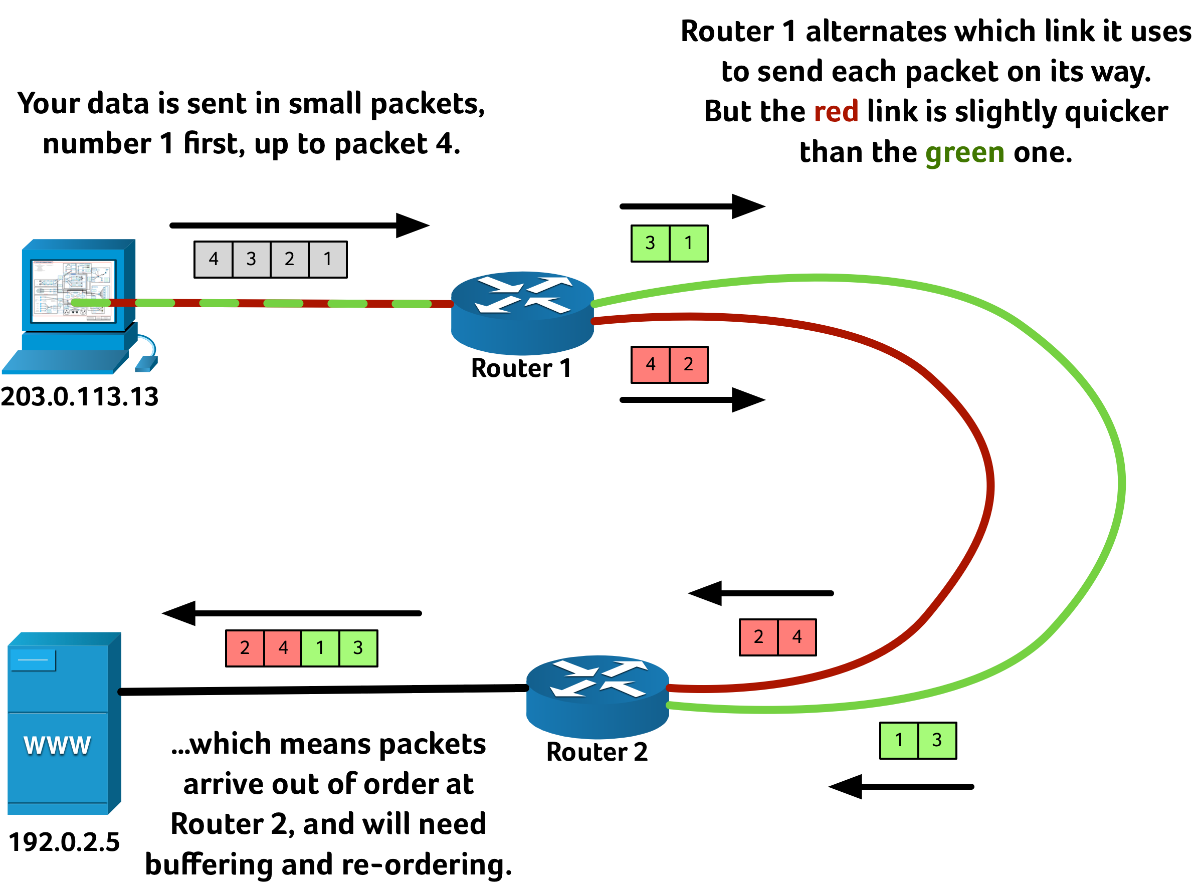
So far LAGs all seem simple enough, and it might seem a fairly obvious way to use an aggregated link is to send alternate packets of data down each link. That can be fine, assuming every path is exactly the same length. But sometimes fibre paths are quite literally different lengths, and so light — your data — takes a different amount of time to propagate depending on which way it goes. It is quite typical to use multiple fibre paths between points to tolerate failure or damage to one route; but if both paths are working fine, wouldn’t it be great to get twice the speed? But the naïve approach of simply sending alternating packets down alternating links might, counterintuitively, slow your network down rather than speed it up:
The problem with out-of-order delivery is that the packets that have “overtaken” (2 and 4 in the diagrams above) need to be buffered in memory until packets 1 and 3 have arrived. Re-ordering takes a small amount temporary storage and CPU time to sort the data back into the correct order, and the so-called “jitter” this adds can potentially be heard on voice-over-IP telephone calls and video-conferencing.
Worse than this, though, is what is likely to happen to a TCP session. The server is expecting to receive 1, 2, 3, 4 in order, but first it receives packets 2 and 4 and so assumes that 1 and 3 were lost en-route. TCP guarantees in-order delivery so the server requests a retransmission of 1 and 3 from the client, only to receive the original 1 and 3 moments later. This extraneous request of 1 and 3 wastes bandwidth. Adding to the frustrations, the perceived “loss” of 1 and 3 potentially causes the data transfer to slow down as TCP’s congestion algorithms believe the link is saturated — a likely cause of why those two packets were “dropped”.
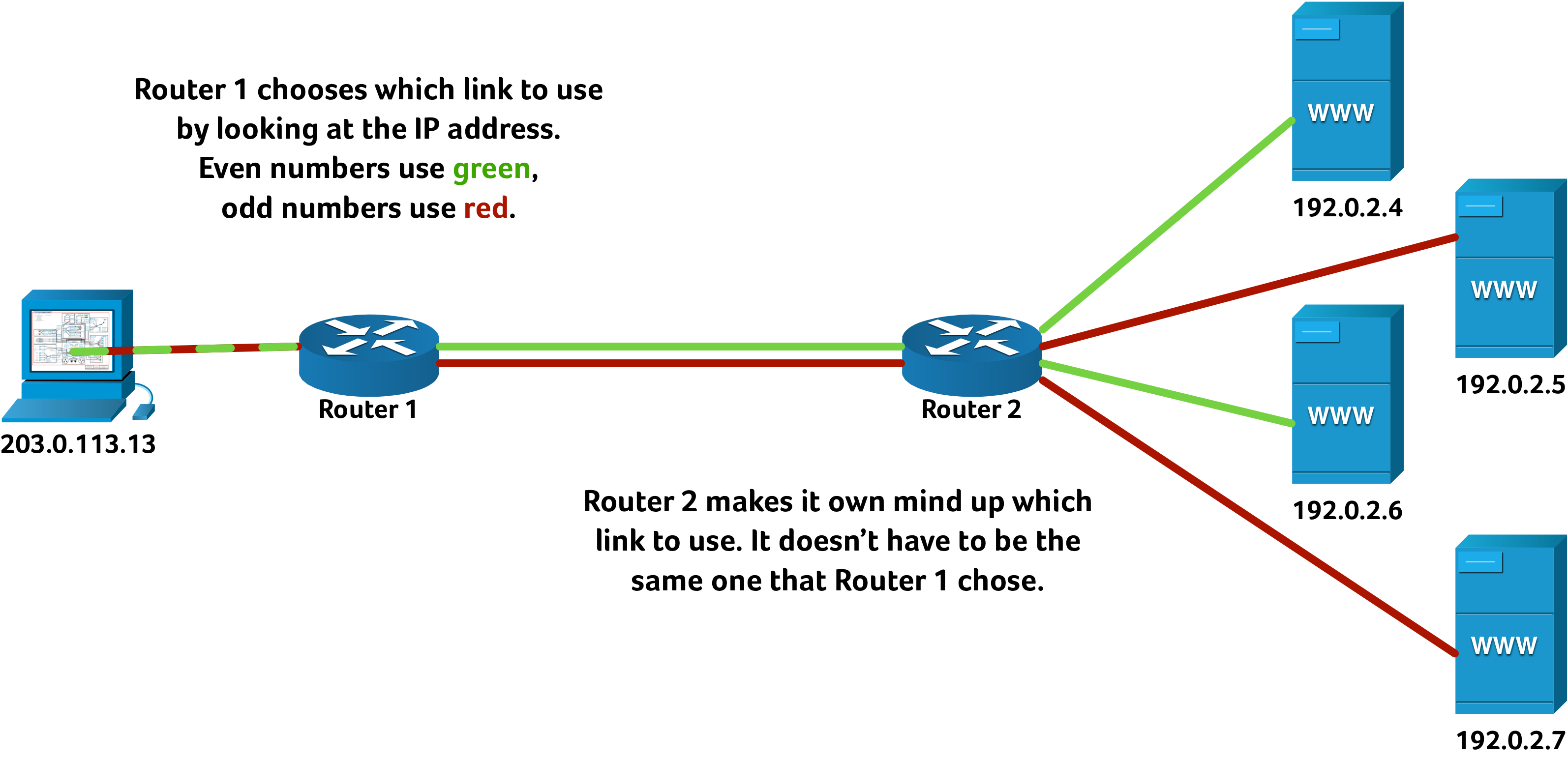
For this reason it can be advantageous to always send one stream of data down the same path — at least while that path is working — and so guarantee in-order delivery. To try to balance which stream of data goes down which link (without having to perform difficult inspection of the data, or hold any state in memory on routers or switches) vendors typically choose a simple calculation. In this example I’m only considering whether the destination IP address is “even” or “odd” — but a real-world implementation would probably use a simple hash function over both source and destination MAC addresses and IP addresses, port and protocol numbers, et cetera.
The above explanation is a highly simplified one, glossing over some of the subtleties network engineers can encounter when different vendors implement different algorithms for link load balancing. Nonetheless it should be enough of a primer that the next part of the story will make sense.
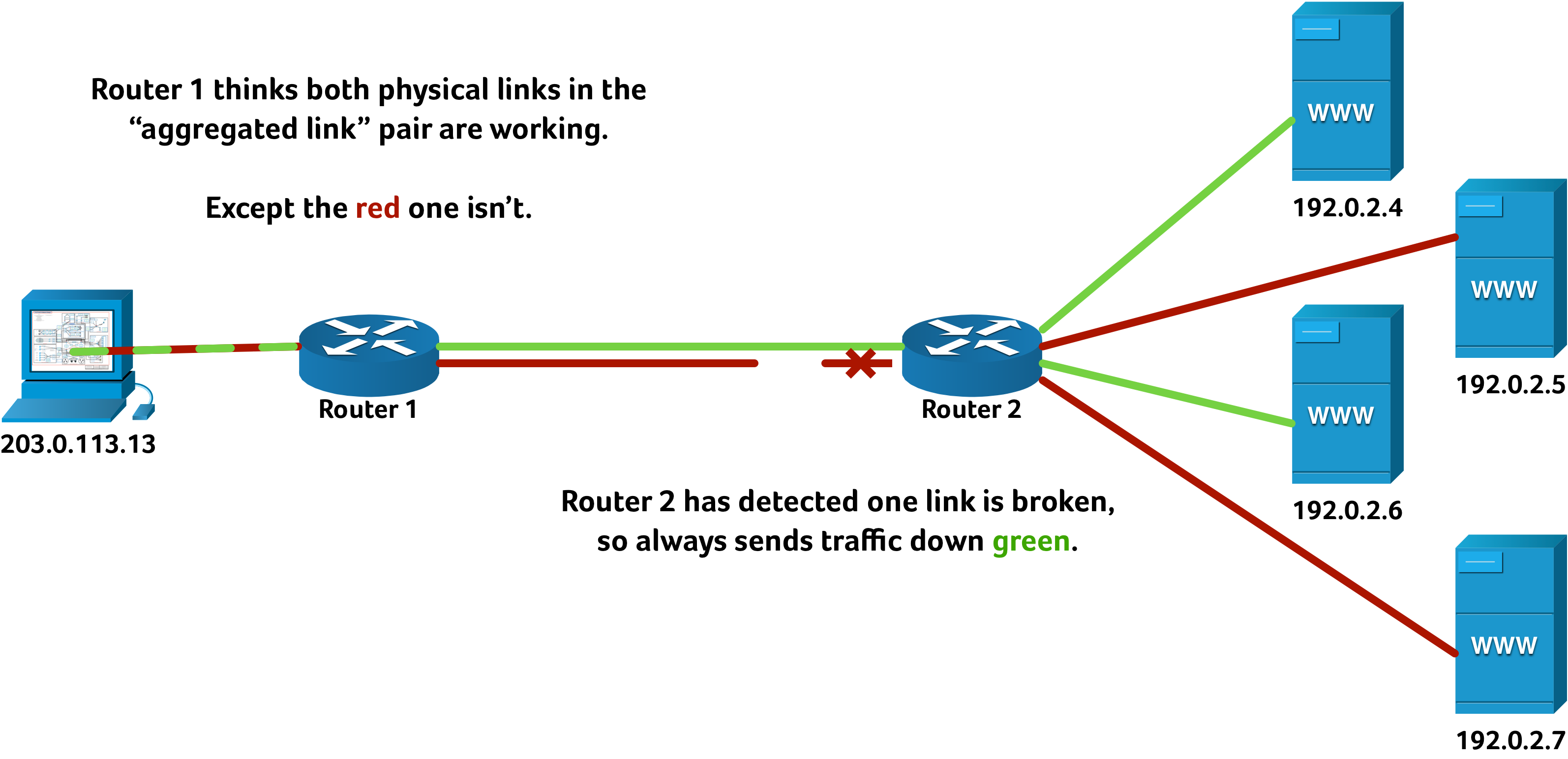
On this particular occasion our monitoring servers noticed some connectivity issues between our Manchester and Geneva hosting hosting infrastructure. What was particularly odd about it was that the alerts showed 100% packet loss… but only about half of the servers were showing as failed. This seems quite counterintuitive at first: why can some servers communicate, but others cannot? This is a fault that we have seen several times before, on everything from small customer networks to national broadband providers to multinational carriers. The answer lies in link aggregation… or perhaps we should call it link aggravation.
Sometimes — due to misconfiguration, vendor interoperability problems, working at the tolerances of the hardware, or otherwise — one end of a LAG thinks all the physical links are working, even when one of them is actually in fault. We saw exactly this kind of behaviour when we tested the affected provider’s link: four consecutive IP addresses were reachable, followed by four consecutive IP addresses where all traffic appeared to be dropped. That pattern repeated over and over throughout the IP address space at one end of the aggregated link.
We quickly took the affected link out of use and notified the relevant provider what we believed to be the fault. It wasn’t long before normal service resumed.
Similar problems can occur in MPLS networks where there is a separate path through the “MPLS cloud” for each direction. There are some technologies that carriers can use to detect and/or mitigate these hiccups, from the simple (such as LACP) to exotic vendor-specific protocols. In effect many of these work by occasionally sending packets down each of the links, and removing from service any physical link which does not work in both directions. Sometimes network engineers do hit an interoperability problem, or an unexpected result of a software engineering decision. This is why monitoring network performance and having teams skilled at interpreting that data is so key to making the Internet work at such a large scale.